
Measures to Prevent Steel Leakage in Porous Plugs
A porous plug is a type of functional refractory material used to inject inert gas into a steel ladle. This process stirs the molten steel, ensuring uniformity in both temperature and chemical composition, while also facilitating the removal of inclusions or the modification of their morphology. This technique is widely employed in the modern metallurgical industry. However, porous plugs have consistently been among the refractory components most likely to cause steel breakouts—a serious safety hazard in ladle operations.
Safety Label for Porous Plug
1. “Safety Label for Porous Plugs”
A material different from that of the porous plug core is embedded within the core. When the porous plug has worn down to the level of this safety indicator—a condition typically identified during the hot repair of a steel ladle—it signals that the safe, usable portion of the plug has been exhausted, indicating that the plug must be replaced or the ladle taken out of service.
Early safety indicators for porous plugs consisted of stainless steel or carbon inserts. As the plug wore down to the indicator, the stainless steel or carbon would melt or oxidize upon contact with the molten steel, creating a void. Molten steel would then enter this void, appearing as a “bright spot” that was easily recognizable to operators on the shop floor. However, these indicators posed a safety risk, as they could potentially lead to steel breakouts. Subsequently, indicators made of materials similar to those of the porous plug itself were introduced. While this prevented the formation of voids at high temperatures, it also made the indicators difficult to detect when the plug reached its wear limit, thereby defeating their purpose. Later, materials with a thermal expansion coefficient similar to that of the porous plug core—but with a significantly different emissivity (blackbody coefficient)—came into use. These offered the advantages of safe operation and easy identification, leading to their adoption by many steel mills; nevertheless, several issues persist during their actual application.
The safety indicators currently employed for porous plugs in steel mills are summarized below:
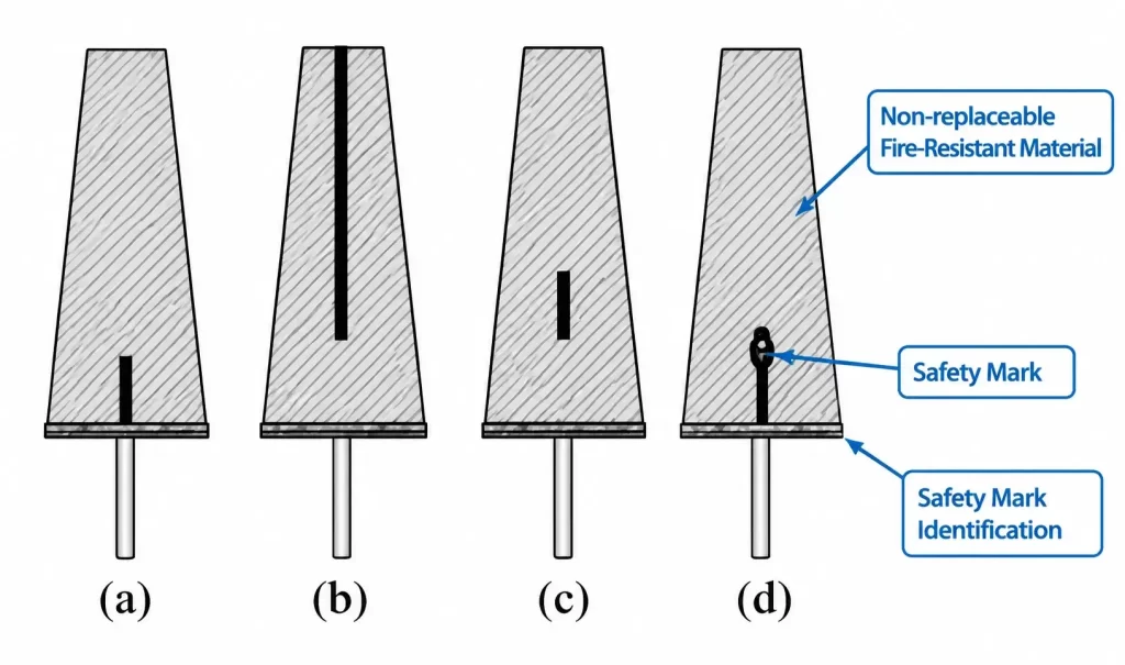
(1) Design of the material, position, and shape of the porous plug safety indicator
Various designs for porous plug safety indicators are illustrated in Figure 1, panels (a) through (d).
In Figure 1(a), the safety indicator poses a significant risk; it may sink or succumb to corrosion, potentially leading to a steel breakout.
As shown in Figure 1(b), the safety indicator (made of stainless steel and appearing as a “bright spot” during operation) remains visible throughout the service life of the porous plug. Once the indicator disappears—signified by the vanishing of the “bright spot”—the plug is considered to have reached a safe limit. However, because the “bright spot” area consistently remains the lowest point on the surface of the porous plug, it is prone to spalling, which negatively impacts the overall service life of the plug.
As illustrated in Figure 1(c), when the porous plug wears down to the level of the safety indicator, a layer of refractory material still remains beneath it. This prevents a steel breakout caused by the sinking of the indicator, thereby significantly enhancing safety.
As shown in Figure 1(d), the safety indicator is designed in a “Y” shape. This configuration effectively prevents the indicator from sinking under the static pressure of the molten steel once it becomes exposed. Furthermore, the upper portion of the indicator is composed of a different refractory material—one with an emissivity (blackness coefficient) that contrasts sharply with that of the porous plug core—making it easily distinguishable during oxygen-lancing maintenance. This further improves the safety of the porous plug.
2. “Anti-Leakage Steel-Component Audible and Visual Alarm Device for Porous Plugs”
The system consists of an alarm probe, a conductive wire, and an alarm unit, positioned on the porous plug core and the ladle shell, respectively. The alarm probe is made of a conductive material, such as metal or graphite, and is secured to the steel casing surrounding the porous plug core during the plug’s manufacturing process. As the porous plug is used, its height gradually decreases. When the level of the molten steel drops to the position of the alarm probe, the molten steel comes into contact with the probe. This creates a complete electrical circuit—comprising the molten steel, the steel casing around the plug core, the alarm probe, the conductive wire, and the external alarm unit—which triggers an audible or visual alert. This intuitive monitoring method helps prevent the risk of steel leakage caused by excessive erosion of the porous plug.
3. “Other Types of Safety Signs”
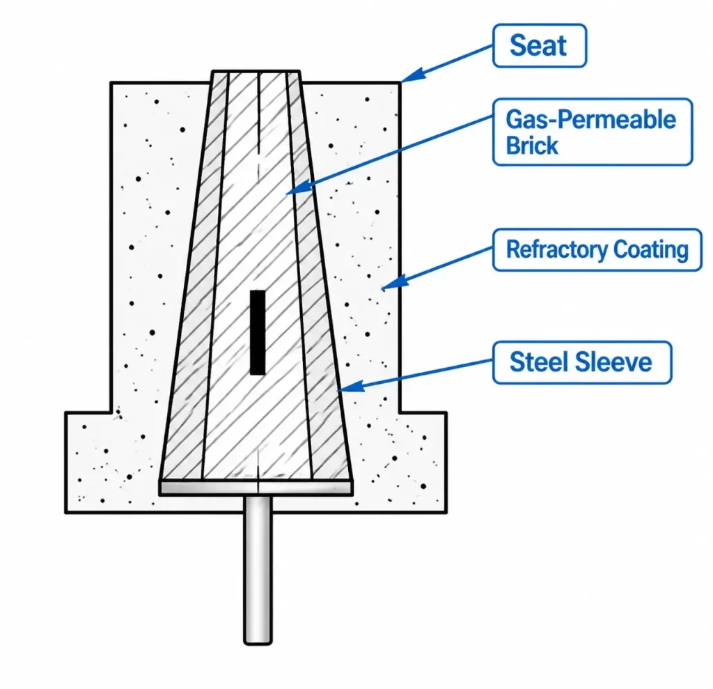
As shown in Figure 2, the steel sleeve for the porous plug core is designed to have a height equivalent to 1/4 to 1/3 of the height of the plug core body, with the space between the sleeve and the core body filled with refractory mortar. On the outer surface of the plug core, starting from the level of the top edge of the steel sleeve and extending upward, a layer of magnesia-chrome or silicon carbide-based refractory coating is applied. This coating possesses an emissivity (blackness coefficient) significantly different from that of the plug core body itself, serving as a safety indicator. This effectively reduces the risk of steel leakage caused by uneven or excessive erosion (burning away) of the porous plug, thereby enhancing its operational safety.
Redesign of the Porous Plug
1. “Redesign of Monolithic Porous Bricks”
Traditional monolithic porous plugs (as shown in Figure 3(a)) have a relatively low safety factor. Under the static pressure of molten steel, they are prone to sinking or detaching from the seating block. Furthermore, molten steel may leak along the interface between the porous plug and the seating block, or through the junction between the plug core and the seating block—all of which pose significant safety risks. To address these issues, the porous plugs shown in Figure 3(b) through (e) have been developed.
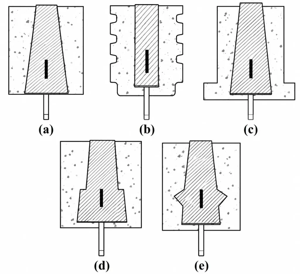
Embedding the porous plug core within the porous plug well block (as shown in Figure 3, (b) through (e)) effectively prevents the core from sinking, which could otherwise lead to a steel breakout. Even in the event of a breakout, the presence of the well block’s refractory material behind the plug core allows on-site personnel time to take corrective action, thereby helping to mitigate potential losses.
As illustrated in Figure 3, (b) through (c), modifying the external geometry of the porous plug well block enhances the bonding between the well block and the surrounding corundum-based self-flowing castable, effectively preventing steel breakouts. Furthermore, should molten steel begin to penetrate the surrounding castable, this design extends the leakage path, thereby reducing the likelihood of steel flowing downward along the edges of the well block.
As shown in Figure 3, (d) through (e), modifying the geometry of the porous plug core—while omitting the steel casing and refractory mortar at the end of the core’s “raised boss” (near the working face)—not only prevents molten steel from seeping through the mortar joints but also effectively stops the core from sinking and causing a breakout. Additionally, this design creates a curved interface between the porous plug and the well block, which further reduces the risk of molten steel leaking along the boundary between the plug core and the well block.
2. “Redesign of Split-Type Porous Bricks”
The split-type porous plug system utilizes an external installation and replacement design, allowing for the replacement of the porous plug while the ladle is still in a hot state. This capability is particularly useful when a plug becomes blocked, suffers from excessive erosion, or reaches the end of its service life, as it facilitates faster turnover of steel ladles. This system offers a relatively low cost of use, ensures a high gas-permeability rate, and maximizes the service life of the steel ladle, making it widely adopted throughout the steel industry. Because the porous plug can be replaced while hot, the system places high demands on both the porous plug seating block and the technical proficiency of the installation personnel. It is critical to ensure that the refractory mortar is applied uniformly across the conical surface of the plug and that the plug is inserted precisely along the central axis of the seating block’s inner bore; failure to do so—such as through uneven mortar joints—could lead to dangerous steel breakouts. Following installation, the seating block must be repaired using patching material that exhibits good sinterability and resistance to erosion.
(1) Improvements to the Split-Type Porous Plug Seating Block
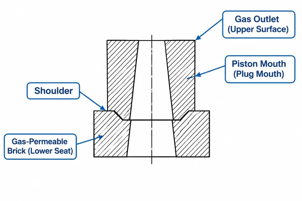
The split-type porous plug seating block has been redesigned into a two-part (upper and lower) assembly (see Figure 4). The interface between the upper and lower blocks features a tongue-and-groove (male-female) joint. This design prevents the risk of steel leakage caused by cracking in the seating block and eliminates the formation of continuous, straight-through gaps between the porous plug and the ladle bottom lining during installation. Furthermore, when the seating block assembly requires replacement during operation, only the upper portion (the porous plug seating block) needs to be replaced, while the lower portion can be reused. This approach reduces production costs and minimizes material waste.
(2) Improvement of the Split-Type Porous Plug Core
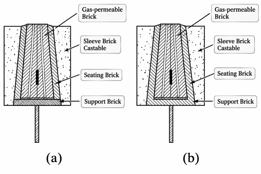
As shown in Figure 5(a), a castable refractory (sleeve castable) is formed around the porous plug core, with an optimal thickness of 20–50 mm; a base brick (support brick) is positioned at the bottom. During the installation of this sleeved porous plug, there is no need to apply refractory mortar to the side surfaces, which prevents the risk of molten steel leaking through mortar joints.
As shown in Figure 5(b), the base brick at the bottom of the porous plug core and the sleeve castable can also be formed as a single, integrated unit, further enhancing the safety of the porous plug.
Conclusion
(1) Appropriate brick designs should be developed based on the specific operating conditions at the steel plant to minimize the risk of steel leakage during the use of porous bricks.
(2) Proper operating procedures for the porous bricks must be ensured on-site. Improper handling should be strictly avoided, as it not only impairs operational efficiency and shortens the service life of the porous bricks but also increases the likelihood of steel leakage.