Long nozzle are subject to complex environmental conditions in the course of their use. Both to face the instantaneous heat brought about by thermal stress and mechanical stress caused by neck fracture or port longitudinal cracking, but also to face the slag on the impregnated parts of the erosion; Not only to face the neck of the inner wall of the steel bulk flow brought about by the local scouring, but also to face the slag line at the inner wall of the steel scouring as well as dissolution of decarburization brought about by the flaring hole. Evaluation of the good and bad of the long nozzle, first of all, the material of the thermal shock stability.
1.Thermal shock damage
Usually long nozzles are used without preheating, with an internal steel flow rate of about 1~8t/min. Therefore, it will produce large thermal stress and mechanical stress. Generally speaking, the thermal stress in the long nozzle is the largest at the beginning of casting, and the damage by thermal shock generally occurs at the beginning of casting. Long nozzle in the initial use, the inner wall contact 1500 ℃ more than the liquid steel, start pouring within a few seconds, long nozzle wall by the liquid steel is heated sharply, and at this time the temperature of the outer wall is still low, will produce a temperature gradient in the internal material. While the inner wall expands, the outer wall can not be synchronized expansion, so that the inner wall will produce compressive stress, while the outer wall is subjected to greater tensile stress. For brittle materials such as refractories, the tensile strength is much lower than the compressive strength. When the tensile stress in the outer wall of the long nozzle exceeds the tensile strength of the refractory material, the outer wall of the long spout will produce longitudinal cracks, neck transverse cracks and other phenomena.
The long spout neck transverse fracture as well as longitudinal cracking at the end is caused by the superposition of thermal and mechanical stresses. Large stresses are generated in the neck area of the long nozzle and around the circumference of the lower spout. This thermal stress is mainly caused by the temperature gradient inside the long nozzle, so the tensile stress (σT) on the outer surface of the long nozzle can be expressed by equation (1):
σT=K·d·E·△T(1)
In equation (1), K is the shape factor, d is the coefficient of thermal expansion, E is the elasticity rate, and △T is the temperature difference inside the long nozzle. Theoretically, the methods to reduce the thermal stress are generally: reduce the coefficient of expansion of the material, reduce the elasticity of the material and reduce the temperature difference inside the material.
The crack stabilization parameter Rst for low-strength ceramics is given in Equation(2).
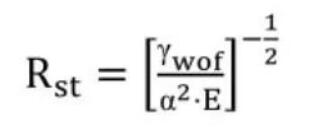
In this equation, E is Young’s modulus of elasticity, α is the linear expansion coefficient, and γwof is the work of fracture. In order to maximize the crack stabilization parameter in refractory design, the generally method is to increase the work of fracture. For long nozzle materials, when the ratio of fracture work to apparent porosity is maximized, it indicates that the material’s resistance to thermal shock and corrosion damage is superior.
In this equation, E is Young’s modulus of elasticity, α is the linear expansion coefficient, and γwof is the work of fracture. In order to maximize the crack stabilization parameter in refractory design, the generally method is to increase the work of fracture. For long nozzle materials, when the ratio of fracture work to apparent porosity is maximized, it indicates that the material’s resistance to thermal shock and corrosion damage is superior.
The article investigates the stresses as well as mechanical stresses in the neck of long nozzle. Using the finite element method, the thermal stress field of a long spout without and with thermal liner in the working condition was simulated, and the effects of thermal shock time, preheating temperature and thermal conductivity of the material on the thermal stress were studied. It is pointed out that the main cause of excessive neck stress is thermal stress and mechanical stress is a secondary factor.
The neck of the ladle shroud is fixed by a support ring and the lower part is inserted below the liquid surface of the ladle. When the slide plate flow control will occur when the bias flow, so that the inner surface of the long spout by the impact of molten steel, resulting in the long nozzle to the neck as a support point of the left and right vibration, so as to produce mechanical stress in its neck. The main factor affecting the vibration is the opening of the ladle slide. It is generally believed that the long nozzle neck transverse breakage is the result of the joint action of thermal stress and mechanical stress, in which the thermal stress is three times of the mechanical stress. So reducing the thermal and mechanical stresses and improving the strength of the material are the solutions to the long nozzle neck transverse breakage.
Testing the thermal shock stability of long nozzle materials is difficult. Some researchers have used to make the specimen into a cylinder with a base plate, heated the cylinder to 1550°C and then immersed it in flowing water. By observing whether water enters the cylinder, to determine whether the cylinder has cracks. The thermal shock stability of the material is better if the cylinder is heated more often.
2.Damaged by erosion
The life of the refractory material and the quality of the billet are closely related to whether or not there is a reaction between the steel and refractory material. Carbon in the steel content is very large, carbon refractory contact steel decarburization process is divided into two forms, dissolution decarburization and reaction decarburization. Dissolution decarburization that is, when the carbonaceous refractory materials and steel contact, graphite to the steel in the process of dissolution, see Formula (3). This direct dissolution process occurs only in the refractory surface and refractory and steel contact at the beginning of the stage and quickly, once the decarburization layer in the refractory surface formation, the material surface only residual oxides, the steel will no longer be in direct contact with graphite.
When the residual oxide is eroded into the steel, the steel will come into contact with the newly exposed graphite, and the dissolution process of the graphite will continue, resulting in erosion of the material. If the residual oxide is not eroded into the steel, the graphite cannot come into contact with the steel because the wetting angle between the steel and the oxide is greater than 90°C, and dissolution into the steel will not occur.
The process of reactive decarburization is related to the type of oxides in the refractory, the composition of the continuous casting molten steel, the surrounding atmosphere and other conditions. Oxygen purging of long nozzle and air intake can lead to oxidative decarburization.
When carbon-containing refractories come into contact with molten steel, the following reactions may occur:
C(s)=C
Carbon dissolved in molten steel species can also be oxidized, with possible oxidation reactions:
2[C]+O2=CO(g)(4)
[C]+(FeO)=CO(g)+Fe
[C]+[O]=CO(g)(6)
The following reactions may occur when the carbon concentration is relatively small:
[C]+2[O]=CO2(g)(7)
Researchers have studied the decarburization of aluminum-carbon materials, and have pointed out that the decarburization of aluminum-carbon materials is mainly due to the dissolution of graphite in the molten steel. When graphite comes into contact with the steel, the graphite dissolves rapidly into the steel because the carbon in the steel is far from saturated. The carbon content of the long nozzle material is very high, and the graphite on the surface after contact with the liquid steel quickly dissolves into the liquid steel, resulting in decarburization. Once the graphite is dissolved, the surface only oxide. The inner surface of the long nozzle appears rough, loose and porous. Rapid steel on the inner surface of the decarburized layer of scouring, resulting in decarburization of the layer quickly fall off, and then cause graphite and steel contact. This process is repeated in a cyclic manner, and the inner wall of the long nozzle is thus porous.
When the combination of the long nozzle outlet and the lower nozzle of ladle is not sealed properly, it will cause local oxidized decarburization due to air leakage, so the sealing or argon blowing of the matching parts is very important. The level of oxygen content in the steel will seriously affect the oxidized decarburization.
When the total oxygen content in the molten steel exceeded the amount of 150 ppm, the erosion of the long nozzle material appeared to intensify. The lower slag of the ladle and the intermediate ladle covering agent work together to erode the long nozzle slag line area. The ability of the aluminum-carbon material to resist slag erosion is strongly related to the slag CaO/SiO2 or Na2O/SiO2, total iron oxide content, particle size, and the microstructure of the material matrix phase and aggregate. The erosion mechanism was explained by observing the erosion state at the material-slag interface.
It is well known that graphite is difficult to be wetted by the slag, but is easily dissolved into the steel. The oxides in refractory materials are not easily dissolved into the molten steel, but are easily wetted by the slag and erosion occurs.In the slag line liquid level, due to the fluctuation of the liquid level, resulting in graphite dissolved into the liquid steel and the oxides by the slag etching process alternately. Therefore, materials that are difficult to be wetted by the slag and dissolve slowly into the liquid steel are helpful in suppressing the etching of the slag line.
Due to the low strength of graphite carbon, it is easily washed away by the high speed steel flow, especially when the flow rate of the steel interface in the long nozzle is high. The decarburization caused by the carbon being washed away by the steel is called scour decarburization.
3.Oxidative damage
Carbon composites have good slag resistance and thermal shock stability due to the presence of graphite. The biggest weakness of graphite is oxidization. In order to reduce the oxidation of carbon-containing materials, small amounts of antioxidants are added. The common ones are Si, Al, Mg, Zr, SiC, B4C, BN and so on. The principle of antioxidant action is considered from the thermodynamic point of view and from the kinetic point of view. The former requires additives or additives and carbon after the reaction of the product and the affinity of oxygen is greater than the affinity of carbon and oxygen at that temperature; the latter requires additives and oxygen, carbon monoxide or carbon after the reaction of the compounds produced after the reaction changes in the microstructure of carbon composite refractory materials, such as blocking the pores of the material to increase the material’s densification, thereby impeding the diffusion of oxygen and the reactants and so on.
Based on the comparison of the magnitude of affinity with oxygen, Si and B4C are used as antioxidants in the long-water-mouth material. After the long spout is sintered, the singlet silicon reacts with carbon to form β-SiC. the remaining silicon powder in the material inhibits the oxidation of carbon, and the reaction formula is shown in Equation (8).
3Si+2CO=SiO2+2SiC(8)
For silicon carbide, the affinity for oxygen is not as great as for carbon. First, solid silicon carbide and gaseous carbon monoxide reaction to generate solid carbon and silicon monoxide gas, generated by the solid carbon deposited on the surface of the silicon carbide, resulting in a decrease in the partial pressure of carbon monoxide and the partial pressure of silicon monoxide increased; silicon monoxide gas to the surrounding diffusion process and carbon monoxide gas reaction products silicon dioxide and carbon deposited. After the above reaction, the carbon monoxide is reduced to carbon, and the volume expands about three times more, blocking part of the pores in the material, improving the densification of the carbon-containing material, and at the same time improving the antioxidant capacity of the carbon-containing material.
At 1800 K, B4C is stable only if the partial pressure of carbon monoxide is less than 10-0.258. However, the partial pressure of carbon monoxide in aluminum carbon material is high. Therefore, B4C is unstable and will react with CO according to equations (9), (10) and (11).
B4C(s)+6CO(g)=2B2O3(g)+7C(s)(9)
B4C(s)+4CO(g)=2B2O2(g)+5C(s)(10)
B4C(s)+4CO(g)=4BO(g)+5C(s)(11)
As the above reaction proceeds, the carbon monoxide in the environment diffuses toward the surface of the boron carbide particles, thereby allowing the above reaction to continue. The generated gaseous B2O2 and gaseous BO diffuse to the surroundings and continue to react with the surrounding CO as shown in equations (12), (13).
B2O2(g)+CO(g)=B2O2(L)+C(s)(12)
2BO(g)+2CO(g)=B2O3(L)+C(s)(13)
The above reaction reduces carbon monoxide to carbon monomers, so the oxidation of carbon is inhibited. The boron trioxide produced can react with the oxides in the material to produce a low-melting phase. The appearance of the low-soluble phase plugs the air holes, which also prevents the intrusion of oxygen.