The high-temperature performance of the lining in medium-frequency coreless induction furnaces primarily depends on the physical and chemical properties, as well as the mineral composition, of the refractory materials used. Given the selection of raw and auxiliary materials, the sintering process is the critical step for achieving a favorable microstructure in the furnace lining, thereby fully leveraging its high-temperature resistance. The degree of densification during lining sintering is influenced by factors such as the chemical composition of the refractory materials, particle size distribution, sintering process, and sintering temperature. Through over two decades of continuous exploration and production trials, a certain factory has developed a rational lining construction and sintering process. This has significantly extended furnace life, with the dry-compacted lining of a 2T medium-frequency furnace achieving an impressive 1,157 furnace cycles (after one intermediate repair), yielding substantial economic benefits.
1.Furnace Maintenance Process
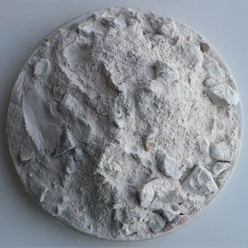
The following treatment is applied to the quartz sand used for furnace construction:
① Manual sorting: Primarily removes lumps and other impurities;
② Magnetic separation: Must completely eliminate magnetic impurities;
③ Dry rammed materials: Must undergo slow drying at 200°C–300°C, maintaining the temperature for at least 4 hours.
2.Selection of Binders
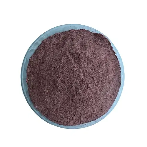
Substitute boric acid (H₃BO₃) with boric anhydride (B₂O₃) as the binder, with an addition rate of 1.1%–1.5%.
3.Selection and Proportioning of Furnace Construction Materials
① Selection of furnace lining materials: Note that not all quartz sand with SiO₂ ≥ 99% is suitable for induction furnace linings. The critical factor is quartz grain size—larger grains with fewer crystal lattice defects are preferable (e.g., crystal quartz sand exhibits high SiO₂ purity, appearing pure white and transparent). Larger furnace capacities demand higher grain quality standards.
② Gradation: Recommended quartz sand gradation for furnace lining: 6-8 mesh: 10%-15% 10-20 mesh: 25%-30% 20-40 mesh: 25%-30% 270 mesh: 25%-30%
4.Bonding of the furnace lining
The quality of the furnace lining sintering directly affects the sintering quality. During sintering, the uniform particle size distribution of the sand prevents segregation. The resulting sand layer exhibits high density, reducing the likelihood of cracks forming after sintering. This contributes to extending the service life of the induction furnace lining.
① Dry-type knotting furnace lining (using a 2-ton medium-frequency coreless induction furnace as an example): Application of coil insulation mortar: The induction coil of a 2-ton medium-frequency coreless induction furnace is coated with a layer of insulation mortar. Compared to conventional insulation materials like mica and glass fiber cloth typically used in induction circuits, coil insulation mortar offers the following advantages:
First, after drying, the 8-15mm thick coil insulation mortar layer exhibits excellent insulating properties, fully replacing mica and glass fiber cloth to serve as the insulating protective layer between the coil and furnace lining. The mortar material possesses a relatively high thermal conductivity coefficient, eliminating concerns that a relatively thick mortar layer might affect the three-layer bond of the hot-face furnace lining.
Second, positioned between the coil and insulation layer, the mortar layer typically operates under low ambient temperatures (<300°C). Occasional contact with molten metal may cause the mortar to release residual moisture, temporarily reducing insulation resistance and triggering an early warning system alert.
Third, leveraging the mortar’s refractoriness exceeding 1800°C, it provides a protective barrier for the coil when molten metal occasionally leaks onto its surface. Upon alarm activation, the mortar layer affords valuable time for incident response.
Fourth, for bottom-top-out furnaces, shaping the mortar with a tapered profile prevents friction between the furnace lining and coils. Simultaneously, its structural strength secures the coils, preventing deformation during operation and furnace construction/dismantling, thereby extending coil lifespan.
Fifth, while the coil and mortar layer serve as the furnace’s permanent fireproof lining—involving high initial costs and extended construction periods—their service life matches that of the coil. Additionally, localized repairs are feasible, thereby reducing overall furnace construction costs. Before dry-tamping the refractory lining, first lay a layer of ceramic fiber board and a layer of glass fiber cloth within the coil insulation layer of the furnace. During installation, manually flatten and compact each layer of material while using spring rings to tension the layers vertically. When tamping the quartz sand, move the spring rings sequentially from top to bottom until the entire lining is fully tamped.
②Bonding the furnace bottom: The furnace bottom is approximately 280mm thick and is filled with sand in four stages. Manual bonding prevents uneven density across different areas, ensuring the furnace lining achieves adequate density after baking and sintering. Therefore, strict control of material thickness is essential. Each sand layer should not exceed 100mm, with furnace walls limited to 60mm or less. Multiple crews operate in shifts, with 4-6 workers per shift. After 30 minutes of ramming, workers rotate positions, moving slowly around the furnace while applying even pressure to prevent density variations.
Once the furnace bottom reaches the required height, level it and place the crucible mold. Ensure the mold is concentric with the induction coil, vertically aligned, and tightly fitted to the furnace base. After adjusting peripheral gaps to be equal, secure it with three wooden wedges and weigh down the center with a suspended load to prevent quartz sand displacement during furnace wall compaction.
③ Building the Furnace Wall: With a lining thickness of 110-120mm, add dry building material in batches, distributing it evenly. Each layer should not exceed 60mm in thickness. Build manually for 15 minutes until level with the top edge of the induction coil. After completion, leave the crucible mold in place; it will serve as an induction heating element during drying and sintering.
5.Baking and Sintering Specifications
To achieve the three-layer structure of the furnace lining, the baking and sintering process is broadly divided into three stages:
① Baking Stage: The crucible mold is heated to 600°C at rates of 25°C/h and 50°C/h, respectively, followed by a 4-hour soak. This aims to completely remove moisture from the furnace lining.
② Semi-sintering stage: Raise temperature to 900°C at 50°C/h, hold for 3 hours; then increase to 1200°C at 100°C/h, hold for 3 hours. Heating rates must be strictly controlled to prevent cracking.
③ Full Sintering Stage: During high-temperature sintering, the sintered structure forms the foundation for extending the crucible’s service life. Insufficient sintered layer thickness at different sintering temperatures significantly reduces service life.
During the baking process of the 2T medium-frequency furnace, approximately 950 kilograms of iron material were added to enhance the heating effect of the induction coil. As baking and sintering continued, low-power electricity generated relatively stable electromagnetic forces to stir the molten iron, ensuring uniform heating of the furnace lining from top to bottom. Strict control of temperatures across the three phase transition zones of quartz sand promoted thorough phase transformation, thereby improving the initial sintering strength of the furnace lining.
Regarding the service life of medium- and industrial-frequency furnace linings, beyond ensuring a complete and properly layered three-layer lining, attention must also be paid to routine operations. Furnace lining construction requires the use of high-quality, clean lining materials, proper mixing ratios, meticulous compaction, scientific baking and sintering protocols, and strict adherence to operational procedures. These measures collectively extend the furnace’s service life.