The continuous casting tundish not only stabilizes and diverts flow but is also crucial for the cleanliness, temperature distribution, and operational stability of the molten steel. The life of the stopper tundish in continuous casting determines the number of continuous casting furnaces per ladle. Due to its unstable lifespan, the stopper tundish can be short, making it impossible to achieve production with fewer pours. Using a stopper tundish for multiple pours not only increases the head and tail billet production and smelting costs, but also seriously impacts production stability, hindering production and increasing tundish refractory materials and the cost per ton of steel smelted. Therefore, technical personnel have addressed the issue of low stopper tundish lifespan and implemented various improvements to the factors affecting stopper tundish lifespan, extending the lifespan of a single stopper tundish to over 30 hours, thereby improving the billet yield and production stability of the continuous casting machine.
Optimization and improvement of tundish structure
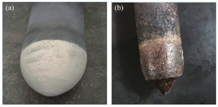
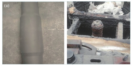
Stopper erosion during the pouring process can be divided into two aspects: plug erosion and slag line erosion. Oxidation of the carbon on the plug surface increases porosity and the plug erosion rate, resulting in a smaller plug. The coating agent within the tundish and inclusions floating on the molten steel surface combine and aggregate at the stopper slag line, forming a “crust.” Especially when pouring Ca-treated steel, CaO can intrude between periclase grains, causing grain separation and material erosion, leading to abnormal erosion at the stopper slag line. The impact zone of the tundish is directly impacted by the molten steel, resulting in relatively active flow and accumulation of inclusions. The tundish structure, constructed with a combination of a frustum-shaped flow stabilizer and a dam, is unable to adapt to the flow characteristics of the molten steel and effectively remove inclusions, resulting in rapid erosion of the stopper tip in the melt pool. During the pouring process, it was found that after the tundish life reached 12 hours, the stopper flow control and multi-flow system failed. Observation of the tundish stopper after use revealed severe erosion of the stopper tip, which deviated significantly from its original shape, leading to failure in subsequent flow control (Figure 1). Furthermore, during the tundish pouring process, the stopper rod’s slag line was severely eroded, with some areas experiencing residual thicknesses reaching 65 mm (Figure 2), severely impacting the tundish’s lifespan and operational safety. To address this issue, the following optimization improvements were implemented to the entire stopper rod.
1.1 Improve the flow field of the tundish
In order to effectively promote the floating of inclusions, improve the removal efficiency of inclusions in molten steel, and reduce the slag crusting rate at the stopper slag line, the overall retaining wall construction method of the impact zone is adopted, and the ladle structure is optimized by changing the diameter and opening position of the small holes of the porous retaining wall.
1.1.2 Design of porous retaining wall
The 6-strand tundish of Tangshan Iron and Steel’s Long Products Division has a steady-state pouring capacity of 40 t and a strand spacing of 1,300 mm.
The main function of the retaining wall in tundish metallurgy is that the retaining wall divides the flow of molten steel in the tundish into two areas: the injection area with strong turbulence and the pouring area with smooth flow. The smooth flow in the pouring area is conducive to the stratification of inclusions and molten steel, and is conducive to the floating removal of inclusions; the retaining wall can make the molten steel flow upward, eliminate short-circuit flow, extend the residence time of the molten steel, and also allow the tundish to have a certain amount of casting residue, which is conducive to the ladle turning.
Fluent software was used to numerically simulate the flow behavior of molten steel in a continuous casting tundish equipped with porous retaining walls. The tundish structure was optimized and the quality of molten steel was improved by changing the shape of the porous retaining walls and the opening angles of the small holes.
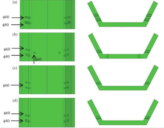
The diversion holes of the porous retaining wall of the tundish play a very important role in the distribution of molten steel in each flow. Figure 3 shows the structural diagrams of four different porous retaining wall schemes.
1.1.3 Analysis of calculation results of flow field in tundish
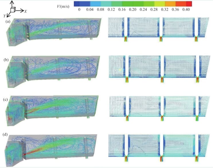
Considering the symmetrical structure of the billet tundish, half of its volume was taken as the simulation object to reduce the computational effort. The calculation results of the flow fields of the four tundishes are shown in Figure 6.
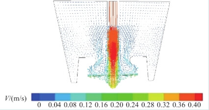
Before the improvement, a combination of a truncated cone flow stabilizer and a dam was used. The velocity streamline of the molten steel entering the truncated cone flow stabilizer is shown in Figure 7. After passing through the impact zone of the tundish, the molten steel directly enters the molten pool area. The molten steel flows actively, the liquid level of the molten steel in the tundish fluctuates greatly, and the residence time of the inclusions is short, which makes it impossible for the inclusions to fully gather and float up.
Figure shows that the overall flow patterns of the molten steel are consistent across the four different retaining wall designs: upon entering the tundish impact zone, the molten steel first collides with the bottom and then moves along the bottom surface. After striking the side wall, the molten steel moves upward along the wall on the ungrooved side. On the grooved side, the molten steel flows out of the turbulence suppressor along the grooves and, after striking the retaining wall, moves upward along the retaining wall, forming a large vortex. This increases the steel’s residence time in the tundish and dissipates some of its turbulent kinetic energy within the impact zone. The molten steel then increases its velocity as it flows through the diversion holes. There are no significant differences among the four designs.
Through the rational design and application of the porous retaining wall, the tundish flow field is optimized, the tundish temperature is uniformed, inclusions are facilitated to accumulate and rise, and the cleanliness of the molten steel in the tundish is improved. Furthermore, the porous retaining wall reduces the amount of slag in the tundish nozzle area. Due to the retaining effect of the retaining wall, the molten steel level in the nozzle area fluctuates minimally, reducing the likelihood of slag roll-up and ensuring stable pouring of the molten steel in the tundish.
1.1.4 Residence time distribution simulation calculation
Considering the symmetric structure of the billet tundish, half of its volume was selected for simulation to reduce computational effort. Streams 4, 5, and 6 were selected for simulation, with stream 5 being the middle stream, representing the flow within the tundish.
Because the overall average residence time (tva) of the tundish represents the average value for the entire tundish and cannot effectively and clearly represent the flow characteristics of individual streams, the average residence time per stream (ta) is used to accurately reflect the flow state of the molten steel. A shorter average residence time per stream is less conducive to uniform steel temperature and composition, as well as inclusion removal. Table 2 shows the RTD calculation results for the four tundish configurations. Compared to the other schemes, scheme C1 has the shortest average residence time per stream, with an average of only 514.6 s for the five streams. Comparing the dead volume ratio, schemes C2 and C3 have higher dead volume ratios of 15.2% and 14.4%, respectively, compared to scheme C4 (12.2%), as an increase in the dead volume ratio impairs steel flow. Furthermore, the overall average standard deviation of the concentrations of each stream is compared. Because a smaller standard deviation indicates a more representative overall average, scheme C4 has a value of only 0.058, demonstrating the best flow consistency among the streams. Taking into account the flow field, average residence time per stream, dead volume, and consistency among the streams, scheme C4 outperforms the other three schemes.
The tundish constructed according to this design reduces the flow of inclusions from the molten steel into the molten pool, effectively promoting their buoyancy and minimizing rod tip erosion. Furthermore, the retaining wall reduces the accumulation of slag in the stopper area, thereby reducing the impact of molten steel on the stopper and the corrosive effects of slag on the stopper, ultimately extending the service life of the stopper.
Stopper improvement
(1) The existing stopper rod length was changed from 1650 mm to 1465 mm. The reduction of the stopper rod length effectively improved the overall use strength of the stopper rod.
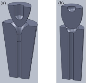
(2) Improvement of the stopper rod plug head: The stopper rod plug head was previously parabolic in shape and had a line contact with the nozzle. After the stopper rod was lifted out after the pouring was stopped, it was found that the plug head was severely corroded. Analysis showed that the plug rod plug head had a poorer fit with the nozzle after the shape change. The contact area between the parabolic plug head and the nozzle was small. When the plug head corroded or the plug head and the nozzle were not aligned, the flow control failure occurred. After the parabolic plug head was optimized to a spherical plug head, the effective contact area between the nozzle and the plug head was increased, and the direct scouring effect of the molten steel on the plug head was reduced. The spherical plug head and the nozzle were in surface contact. When a part of the plug head corroded, the plug head and the nozzle had a small change in shape. The other parts could still be normally combined with the nozzle, achieving a slight change in the flow control accuracy of the stopper rod and continuing to ensure the flow control effect of the stopper rod.
(3) To address the erosion of the plug, the plug material was selected from fused magnesia alumina spinel, the mass fraction of MgO was increased to 70%, and large-crystal fused magnesia with a higher MgO content was used. The mass fraction of carbon in the plug was reduced from 12% to 8% to reduce the probability of reaction between oxygen and impurities in the molten steel and the carbon in the plug. The silicon content was strictly controlled, and a higher-grade silicon-free antioxidant was used to improve the oxidation resistance and strength of the plug. The oxidation resistance of the stopper rod coating was also improved. The erosion of the plug after material optimization is shown in Figure 9.
(4) Thickening the stopper slag line: In order to improve the erosion resistance of the stopper slag line, the outer layer of the stopper slag line is thickened. On the basis of the overall stopper length remaining unchanged, the slag line thickness is increased from the original size of 150 to 187 mm, thereby improving the erosion resistance of the stopper slag line.
Improvements to the impact zone and flow stabilizer
(1) The impact zone of the tundish is directly affected by the erosion of the molten steel, and the molten steel flow in this area is relatively active. In order to improve the erosion resistance and erosion resistance of the impact zone, a protective plate for the impact zone is designed and installed. The dry material distribution height of the lower impact zone of the tundish is 550 mm. The protective plate is placed in the gap between the mold and the permanent layer; there is a 10 mm gap between the protective plate and the permanent layer to ensure that the protective plate reaches the corner position of the tundish. Then, the dry material of the tundish is poured in to fix the protective plate.
(2) The flow stabilizer can prolong the residence time of the molten steel in the tundish, which is conducive to the aggregation and floating of inclusions. At the same time, it can slow down the impact, splashing and fluctuation caused by the impact of the molten steel and the speed of the upward flow, reducing the slag rolling of the molten steel. In addition, the flow stabilizer is conducive to the uniformity of the molten steel composition and molten steel temperature, reducing the erosion and erosion of the refractory material in the tundish injection zone, and slowing down the formation of “convergence vortex”. In order to avoid the breakdown of the flow stabilizer in the later stage of pouring, the flow stabilizer was improved and its structure and material were optimized: the cup edge of the flow stabilizer was designed to be concave, and a high-performance impact plate was pre-laid on the bottom of the flow stabilizer before pouring. Three 90 mm impact plates were added to slow down the mechanical scouring of the molten steel on the ladle and improve the impact resistance of the bottom of the flow stabilizer; the impact plate inside the flow stabilizer was designed to be a truncated cone shape to prevent it from floating under the impact of strong steel flow; at the same time, 3% magnesium oxide was added to the castable used in the flow stabilizer on the basis of the original formula to improve its high-temperature flexural strength.
Improvement measures for the tundish working layer
In the early stage, magnesium dry material was used in the tundish. However, after 12 hours, the strength of the magnesium dry material decreased and its corrosion resistance was relatively poor. At the same time, under the working conditions of high temperature and high speed molten steel and the working layer, the working layer was frequently oxidized. In addition, slag erosion of the working layer was also the main reason for the damage of the working layer. In the past, due to the short vibration and knotting time of the dry material in the tundish wall, the dry material structure was relatively loose. After baking, it was only connected by the residual carbon chain formed by resin solidification. The residual carbon volatilized at high temperature, which made the dry material’s anti-erosion erosion effect poor. The covering agent and the steel liquid inclusions penetrated into the working layer and reacted with it to form low-melting-point substances that dissolved into the slag, resulting in abnormal erosion and peeling of the working layer [5-6]. To this end, the following measures were taken:
(1) The working layer of the stopper tundish was repaired and built according to the slider package. The slider was used to package the working layer. The thickness of the working layer was increased from 80 mm to 110 mm, thereby increasing the thickness of the tundish working layer.
(2) The vibration time of the working layer mold was increased from 5 min to 8 min. Improve the density and bonding strength of the vibrating dry material, thereby improving the anti-scouring performance of the working layer and reducing the erosion rate of the working layer by steel slag.
(3) Improve the working layer of the stopper rod ladle. First, use high-purity large-crystal fused magnesia as the main raw material of the working layer to reduce impurities such as SiO2 and CaO, and greatly improve the erosion resistance of the dry material; second, introduce a small amount of Al2O3 nanopowder into the magnesia raw material to improve the sintering performance of the magnesia, and use the spinel whiskers formed in the ladle working layer during the low-temperature baking process to achieve the self-densification and self-repair enhancement effect, thereby improving the high-temperature mechanical properties of the material, inhibiting the slag from penetrating into the interior, and improving the erosion resistance of the dry material [4-5]; third, introduce special additives into the dry material formula so that it has a buffering stress effect through the solid solution-desolvation reaction caused by self-sintering during the working process, reducing the abnormal structural erosion and spalling of the refractory material. Among them, it is required that w(MgO)+w(Al2O3)+w(SiO2) in the additives ≥88%, w(C)≤10%.
Improvement measures for submerged nozzles
In the early stage, the submerged nozzle had problems such as perforation, fracture, and deep slag line, resulting in a short service life. As the pouring time increased, the submerged nozzle had to be replaced frequently. However, nozzle replacement is an unstable pouring state, during which it is easy to cause steel leakage accidents such as adhesion and inclusion. In response to the above problems, the submerged nozzle was improved from the following aspects.
(1) In response to the problems of perforation and fracture of the submerged nozzle, analysis of the residual samples after use showed that there was obvious eccentric expansion. On the one hand, the material scheme of the nozzle body was changed to improve the anti-scouring property of the body, and a layer of anti-scouring lining and high thermal stability lining was compounded on the nozzle body and slag line. On the other hand, the inner diameter size of the submerged nozzle bowl was adjusted to make it more closely matched with the lower nozzle of the tundish to prevent oxygen absorption during the steel pouring process.
(2) By lifting the middle ladle car, the single-slag line casting of the submerged nozzle was changed to a double-slag line casting. The original insertion depth of the submerged nozzle was 90 mm. After optimization, the insertion depths were 100 and 80 mm respectively, thereby improving the service life of the submerged nozzle. Through the above measures, the average service life of the submerged nozzle during the stopper ladle casting process reached 9.6 hours. At the same time, in order to ensure the continuity of production and avoid abnormal casting caused by quality fluctuations of individual branch nozzles during the production process of the submerged nozzle, a quartz baking-free nozzle was independently developed. When the submerged nozzle suddenly has quality problems, the quartz baking-free nozzle can be used directly without baking, which improves the on-site staff’s ability to deal with the production impact caused by the breakage and perforation of the submerged nozzle and ensures the smooth operation of continuous casting.
Improvement measures for upper nozzle and well bricks
During the pouring process of the stopper rod ladle, it is often found that the upper nozzle has perforation, which leads to the suspension of pouring, as shown in Figure 10. The following improvements have been made.
(1) In order to improve the strength of the upper nozzle and solve the problem of cracking in the middle and lower part of the upper nozzle, a steel shell is added to the lower part of the nozzle (Figure 11). At the same time, the isostatic pressing process is adopted in the production process of the upper nozzle, and the molding pressure is increased from 110 to 150 MPa. Practice has shown that the lower end cracking phenomenon no longer occurs after adding the steel shell.
(2) The upper nozzle of the tundish adopts a composite double-layer zirconium structure, and composite metal micropowder is introduced into the bowl material to improve the service life of the upper nozzle [7-8].
(3) The baking time of the stopper rod ladle is extended. Considering the actual calorific value of the coal gas, it is increased from the original 3.5~4.0 h to an average of 5.5 h.
(4) At the same time, a sealing gasket is independently designed and manufactured. The sealing gasket is added at the suction position during the negative pressure baking of the stopper rod ladle to ensure the sealing performance and increase the baking temperature of the upper nozzle to avoid the upper nozzle from bursting due to the drastic temperature change when pouring.
Through the above measures, the average service life of the stopper rod tundish was increased from 15.12 h to 30.25 h, realizing the long life and high efficiency production of the square billet stopper rod tundish.
Conclusions
(1) By changing the diameter and opening position of the porous retaining wall holes, the structure of the tundish is optimized, inclusions are effectively removed, and the erosion of the working layer and the stopper rod is reduced;
(2) By improving the overall stopper rod slag line and the plug head form and material, the durability of the stopper rod is improved;
(3) By improving the impact zone repair method and the flow stabilizer method, the service life of the impact zone and the flow stabilizer is improved;
(4) By optimizing the working layer of the stopper rod package, the service life of the working layer of the stopper rod tundish is improved, and the erosion resistance of the working layer is improved;
(5) By optimizing the use of the submerged nozzle and developing a quartz bake-free nozzle, the service life of the submerged nozzle is improved;
(6) By optimizing the production and processing technology of the upper nozzle and the on-site operation, the service life of the upper nozzle is improved.
Through the above measures, the average service life of the stopper rod tundish was increased from 15.12 h to 30.25 h, realizing the long life and high efficiency production of the square billet stopper rod tundish.