The integrated taphole plug is one of the most critical control components in continuous casting operations. Installed within the ladle, it works in conjunction with the internal submerged nozzle or the ladle top nozzle to regulate molten steel flow from the ladle to the mold. This ensures stable flow surfaces within the mold and maintains process stability throughout continuous casting. Due to the non-replaceable nature of the plug rod during operation, any malfunction can lead to loss of control over the steel flow or even halting of pouring, causing the continuous casting process to interrupt. This can result in severe accidents or significant economic losses. This paper analyzes issues encountered during the application of integrated ladle plug rods in dozens of domestic and international steel enterprises and proposes effective countermeasures for various problems, serving as a reference for learning and application.
Main problems in the use of tundish integral stopper
1.Problems encountered in the use of the stopper head
The rod tip is a critical component of the rod. Working in conjunction with the water inlet, it controls flow and therefore requires excellent erosion resistance. Rod tips are typically made from materials such as aluminum carbon, magnesium carbon, spinel carbon, and zirconium carbon, with a carbon content typically significantly lower than that of the rod body. Problems with the rod tip during use in tundish integral rods primarily include severe rod tip erosion and rod tipping.
A. The rod tip is severely eroded
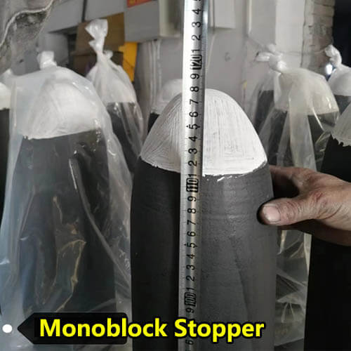
When the plug rod tip is severely eroded, the rounded arc of the tip can be seen to have been worn into a concave shape. This altered shape of the monoblock stopper tip results in poor mating with the inlet port rim, leading to unstable flow control or even loss of flow control function. The rammer height decreased from 1250mm to 1225mm, with the rammer head eroded by 25mm. This height reduction prevents effective flow control and hinders proper closure during pouring stoppages.
B. Turn the stopper rod around
The stopper head separated from the rod body, reducing the stopper height from 1725 mm to 1600 mm, with the head losing 125 mm. Consequently, the stopper could not properly control the flow, causing the continuous casting process to halt.
2. Issues encountered during use of the plug rod
The ram body consists of the ram body material and the slag line material. The ram body requires adequate strength to prevent breakage during operation, typically made of aluminum-carbon material; the slag line requires excellent resistance to slag erosion, commonly composed of spinel-carbon or zirconium-carbon materials. The primary issue encountered during ram body use is transverse breakage, which can occur either at the ram body section or the slag line section.
For monolithic plugs, when transverse breakage occurs during steel pouring despite sufficient wall thickness, it typically happens at the midpoint of the plug body. The fracture surface is clean and exhibits a knife-edge appearance.
3.Problems encountered in the use of stopper rod connectors
Stopper connections typically include metal wire plugs, carbon or ceramic plugs, and pin holes. Metal wire plugs are the most widely used, with the M39 plug being the most commonly used. Stopper connectors play a crucial role in the continuous casting process; a loose connection or detachment can cause continuous casting to cease. Common problems with stopper connectors include melting of the connector and cracking of the stopper end.
Analysis of main problems encountered in use and improvement measures
1.Analysis of problems in the use of plug rod heads and improvement measures
1.1 Analysis of severe rod end erosion and improvement measures
The compatibility between the material of the rod tip and the continuous casting process is a critical factor affecting rod tip erosion. Generally, the material selection should be based on the reaction between the cast steel grade and the refractory materials. Rod tip erosion primarily involves three aspects: physical erosion, carbon oxidation, and oxide reactions. At higher vacuum levels, MgO reacts with carbon, accelerating erosion of the rod tip. When molten steel contains high calcium levels, reactions with Al₂O₃ accelerate erosion. Elevated oxygen content in the steel accelerates carbon volatilization, further hastening erosion. Appropriate rod tip materials should be selected based on specific steel grades and operating conditions. Al₂O₃-C rod tips are more suitable for A1-killed steel than MgO-C rod tips, while the latter are highly suitable for calcium-treated steel. During steel pouring, the thin slag film formed on the rod tip surface—comprising CaO-Al₂O₃ compounds and MA, M₂S—effectively protects the rod tip from molten steel erosion. ZrO₂-C nozzles demonstrate superior adaptability to complex molten steel compositions in continuous casting environments, primarily due to zirconia’s exceptional erosion resistance.
Excessive baking duration also contributes to abnormal erosion of stopper nozzles. Typically, baking time for stopper rods is around 2 hours. Baking exceeding 4 hours can damage the rod’s anti-oxidation glaze layer, leading to oxidation progressing from the surface to the inner layers of the rod tip. Furthermore, as baking time increases, the depth of oxidation in the rod tip deepens. Once oxidized, the carbon bonding in the rod tip material is disrupted, causing rapid deterioration under the high-velocity erosion of molten steel.
1.2 Analysis of causes for rod tip reversal and improvement measures
There are numerous causes for the tip of a solid stopper rod to turn back, generally falling into two categories: thermal stress and mechanical stress.
The phenomenon of stopper rod tip turning back due to thermal stress is relatively common. Before use, stopper rods typically undergo approximately 2 hours of baking. The final temperature achieved during baking is critical, generally needing to reach 1100°C. If the baking temperature is insufficient, the plug rod is suddenly heated upon contact with high-temperature molten steel during pouring. Due to differing thermal expansion coefficients between the tip and body, thermal stresses develop internally. This stress concentration causes the plug rod to tip over. The key to resolving this issue is strictly adhering to the plug rod baking protocol.
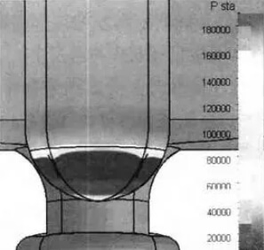
Additionally, some steel mills require baking the plug rod in its closed state, which prevents effective baking of the tip section. This also leads to thermal stress concentration during pouring, causing the plug rod to break off. Figure 2 shows the numerical simulation state during closed-baking, revealing that the baking temperature at the tip section remains relatively low.
There are numerous instances where stopper rods fracture due to mechanical stress. Installing the rod head off-center relative to the water inlet, striking the water inlet with the rod during blockage clearance, or applying excessive force during quick-change operations on submerged water inlets can all cause the rod head to detach.
2.Analysis of rod usage problems and improvement measures
The main causes of stopper rod breakage are thermal and mechanical stress fractures. Thermal stress is primarily influenced by the baking time and temperature of the stopper rod. Mechanical stress fractures can be caused by a variety of factors, including misalignment between the stopper rod and the nozzle, excessive operating force, and tundish crusting that prevents the stopper rod from being raised or lowered. These issues can be addressed by strictly enforcing baking procedures, training key stopper operators, and improving the continuous casting process.
Cross-sectional breakage of stopper rods is common during continuous casting, with a high proportion of breakages caused by thermal stress, mechanical stress, and chemical corrosion.
Abnormal erosion of the stopper slag line is primarily caused by inappropriate material selection and incorrect operation. First, the stopper slag line material must be suitable for the continuous casting process. Choosing the appropriate slag line material based on the composition of the continuous casting slag and tundish coating is essential. For example, steel grades with high MnO content should avoid materials containing SiO2, SiC, and elemental Si powder to prevent the formation of a low-melting phase of silicon, manganese, and oxygen, which can exacerbate erosion.
Ladle slag discharge is also a common cause of abnormal stopper erosion. Failure of the automatic ladle slag discharge detection system or improper control of ladle slag discharge during continuous casting can result in a large amount of ladle slag flowing into the tundish. Furthermore, due to poor slag retaining effect or inadequate slag removal from the slag retaining plate, ladle slag accumulates around the stopper, causing abnormal erosion of the stopper slag line.
Adding mold slag to the tundish is also a cause of abnormal stopper slag line erosion. Low tundish temperatures and other factors can cause crusting on the tundish surface during continuous casting. In such cases, operators sometimes add mold slag, which has a lower melting point, to prevent crusting. Due to the strong corrosiveness of the mold protection slag, the stopper slag line is abnormally eroded.
3.Analysis of connector usage problems and improvement measures
Problems with the stopper rod connector include cross-sectioning of the rod end and melting of the lead screw, both of which occur frequently.
The primary cause of cross-section at the stopper rod plug is poor installation. Excessive tightening force on the lead screw during installation, or bumps during commissioning, can all cause the end of the stopper rod to break. The end of the stopper rod contains a metal wire plug, embedded during the rod forming process, making the plug a relatively weak area on the rod body. During installation, proper force should be applied and the rod end should be inspected after installation to remove any cracks promptly.
The root cause of melting at the stopper rod connector is a problem with the rod design. The rod is designed to be short, preventing the end from protruding from the cladding cover. During high-temperature baking or use, the connector overheats, causing the lead screw to melt. The fundamental solution to this problem is to lengthen the rod so that the connector is exposed to the cladding cover. To lengthen the stopper rod, the stopper rod mechanism must be changed. Some steel mills are limited by the fact that the height of the tundish stopper rod mechanism is fixed. The stopper rod can be made higher by making the cross arm of the stopper rod into a step shape, as shown in Figure 3.
In addition, applying fireclay between the stopper rod, lead screw, and connector, and replacing graphite gaskets with asbestos gaskets between the lead screw and connector are convenient temporary measures. Applying fireclay between the lead screw and connector can prevent heat transfer to a certain extent, reducing the risk of connector melting; replacing graphite gaskets that are easily burned and release heat with asbestos gaskets can also reduce the risk of connector melting; however, these two measures cannot fundamentally solve the problem.